Xanadu Rocket
2026
Xanadu Rocket Abstract
The objective of this project was to design and validate a 30-inch G-class rocket as part of Project Daedalus at the Rocket Propulsion Laboratory. The rocket features NACA 0012 fins modeled in SolidWorks, optimized CG/CP stability margins, and a recovery system engineered to cap descent at 15 ft/s. Iterative configuration testing in OpenRocket and structural design refinements maintained stability throughout the flight profile.
Design Process
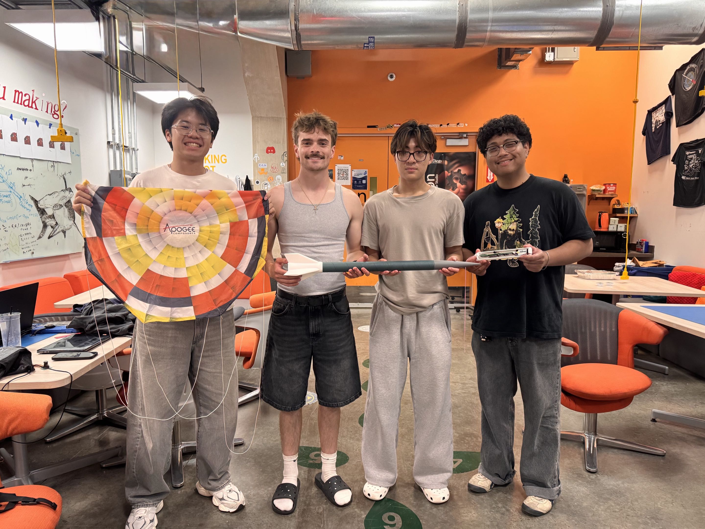
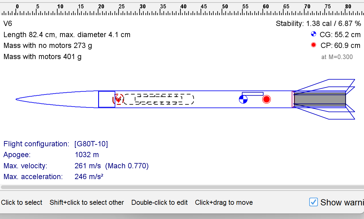
The process started off with the four of us putting our heads together to think about how to make the coolest rocket. Before even figuring out how to make a rocket fly successfully, we wanted to make sure that our rocket was worth coming back to work on. Eventually after some intensive brainstorming, we decided we wanted a super fast rocket that looked cool. Simple as that since it really was our first time building a rocket. What came next was the actual planning of the logistics. We created an OpenRocket simulation starting off with the definite variables first like the G80T-10 motor and the 38 mm blue tube. Based on that, we created our first iteration of the rocket. Looking back now, we had the idea that a longer and bigger rocket would look cooler. As you’ll see with the final design, we ended up cutting down the length of the rocket to get rid of empty space within the airframe, reducing drag and making the rocket go faster, which was backed by our OpenRocket numbers.
Avionics
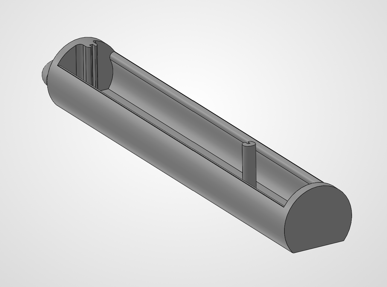
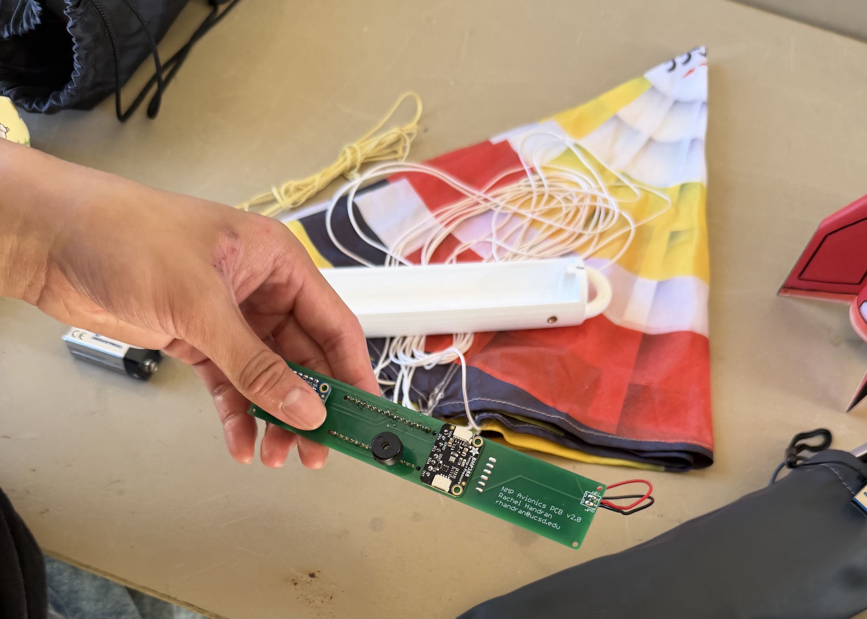
In terms of avionics, we wanted to have flight data at the end of the whole project. We implemented the following components: - Adafruit BMP388 Precision Barometric Pressure Sensor (altimeter and temperature) - Adafruit BNO055 (accelerometer, gyroscope, and magnetometer) - Adafruit Ultimate GPS Breakout (GPS module using laptop as receiver) - Piezo Buzzer (sign of life for avionics) - Arduino Nano These components were all soldered onto a custom PCB and slotted into a self-modeled avionics chamber. After some tinkering and testing with the avionics and the code in Arduino IDE, all of the components were working in isolation. The main issue that eventually showed up was that the GPS module couldn’t work alongside the other components because it drew too much current for the 9V battery to reliably supply. The other option was to use two Arduino Nanos in the circuit. This eventually led to us deciding to ditch the GPS module since the flight data mattered more to us which was unfortunate.
Fin Can
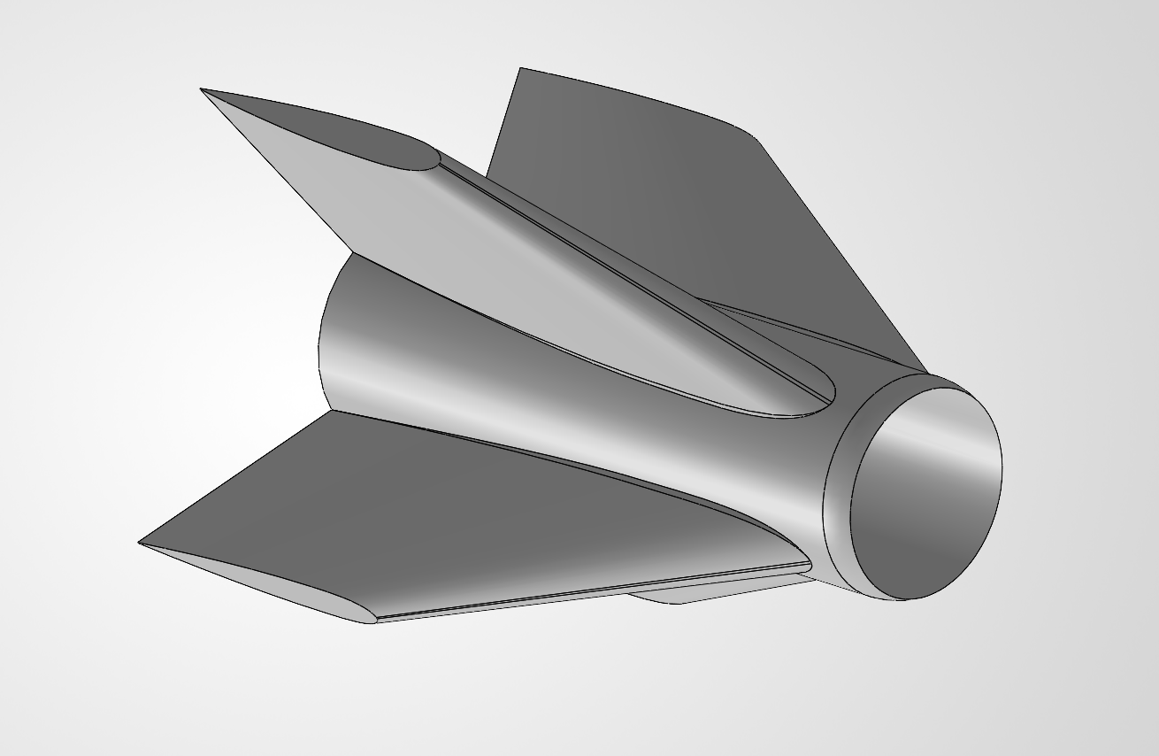
The fin can is one of the parts that I am very proud of in terms of design. I used a NACA 0012 curve I found and imported the airfoil coordinates into SolidWorks to build the fin can. It took some trial and error since I learned that SolidWorks couldn’t compute the perfectly sharp corner created by the airfoil. This was simply solved by sketching a rounded edge that was practically negligible once 3D printed. Although I was really happy with the shape of the model and how it came out, in retrospect, this airfoil may not have been the best option. I initially chose it since it was a tested airfoil that had been proven to work, but with what I know now, the 12% thickness ratio may have been thicker than necessary for a small G-class rocket. A thinner airfoil might’ve yielded similar stability while also reducing drag.
Nose Cone
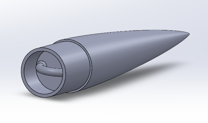
The nose cone was relatively straightforward. I based the length of the nose cone on a fineness ratio of 5:1 and used the von Kármán shape. This was based on a NASA paper outlining what a sufficient fineness ratio and nose cone shape would be for subsonic speeds. Inside the nosecone, I also made sure to add a loop to secure the shock cord too including some fillets at the base to increase the structural integrity.
Fabrication
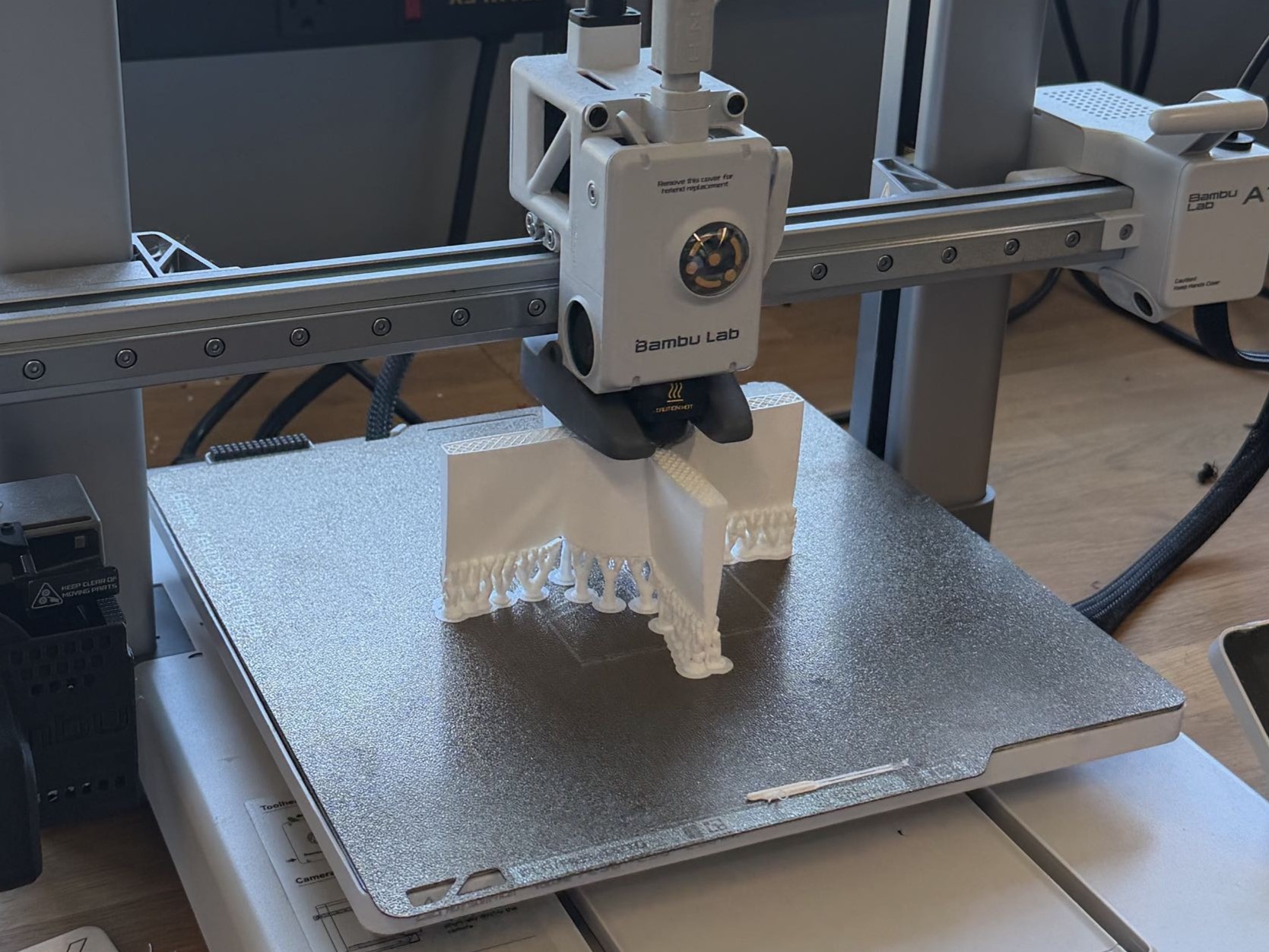
When it came to the fabrication of the rocket, we went through multiple iterations of the 3D prints to identify the right tolerances and remedy print failures. We also reiterated the OpenRocket design multiple times to ensure we stayed between 1.2–1.5 calibers of stability. We adjusted the weight of the 3D prints, changed the length of the body tube, and moved around component positioning to achieve our target stability. This proved to be relatively successful since our theoretical center of gravity (COG) was only 0.2 cm off from the actual COG on launch day.
Launch Day
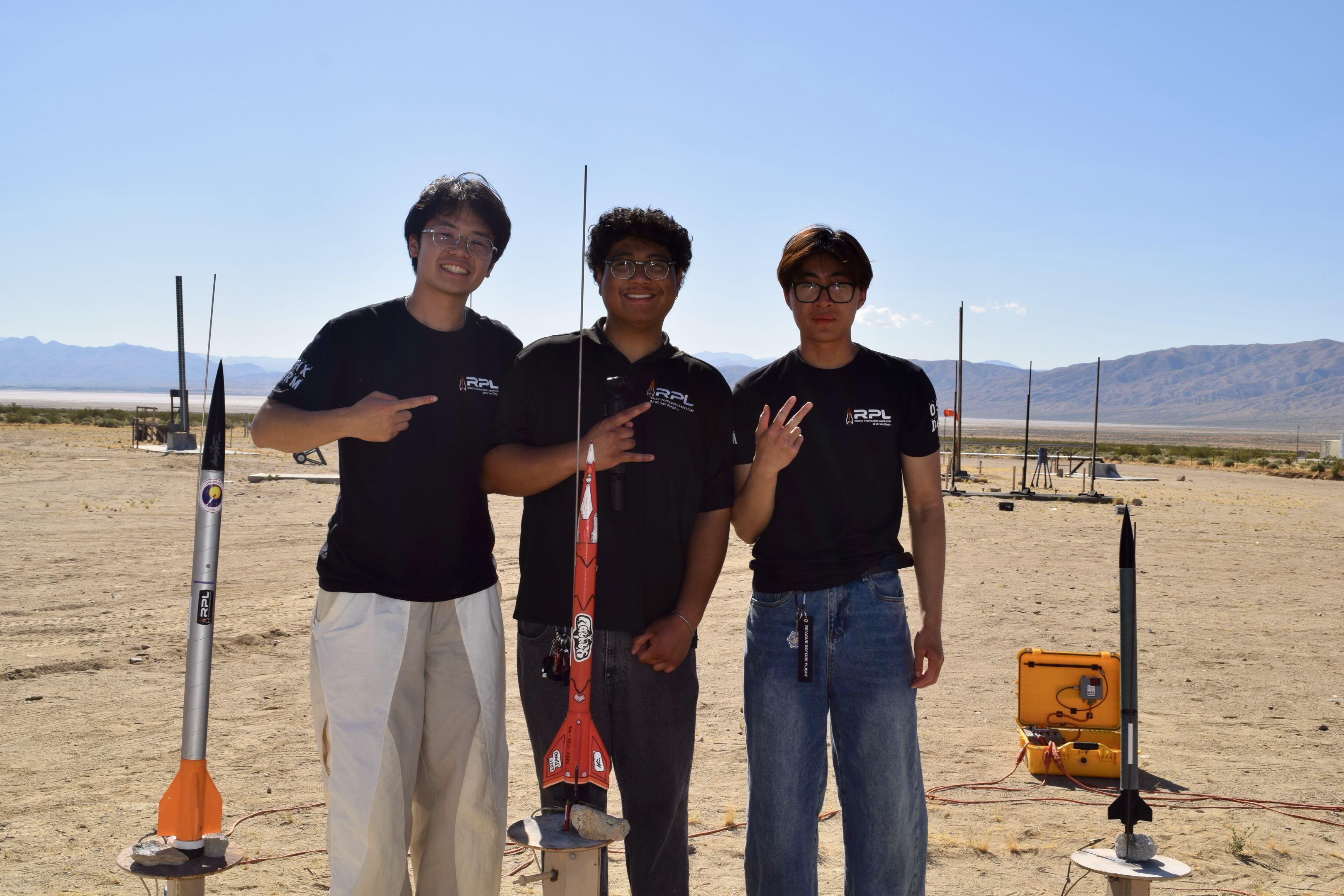
Launch day was officially a success. After prepping our rocket and putting the recovery wadding and parachute into the body tube, we capped it with the nose cone and prepared to set the rocket onto the launch stand. The launch was a success, with the rocket flying straight up without tumbling.
Recovery
At apogee, we could visibly see the parachute open. This was amazing news. It didn’t last, however, since the next step was to actually retrieve the rocket. The unfortunate part was that since it had opened so high up, it got carried very far by the wind. That day, it was in the mid-90s Fahrenheit in the middle of the Mojave Desert, so we were told that recovery wasn’t possible since the hiking distance was unknown. My team and I were both ecstatic that the launch went well but also disappointed that we wouldn’t be able to retrieve the rocket. All of our flight data was in there, donated to the desert. What we did recover however was the experience along the way.
Final Reflection
Building this rocket was my first time working hands-on with a legitimate rocket motor. It was fascinating to see how quickly the rocket actually came together once all the planning was done. This showed me that planning was the majority of what made the rocket actually fly successfully. Anyone could put together a rocket like Legos, but it’s the research that goes into making the rocket launch smoothly that shows its real difficulty. Overall, I thoroughly enjoyed building and launching this rocket—so much so that I’m already working on my new L1 rocket, which will be launched in October 2026.